Olive for JNCIE
I met Olive the first time and played with it for a while, I told myself there should be several different ways in using this emulator to make me able to practice for JNCIE lab. So I'm sharing those here, and if you are in the middle of the journey, please provide your feedback whether all features required in lab can be tested with my ways.
This topology drawing is taken from JNCIE study guide.
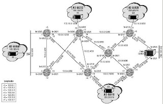
As you can see, there are 7 core routers in the middle, 4 routers for external AS, and 1 router called Data Center. Most of the links are point-to-point. Knowing this fact, I believe we just need 1 ethernet interface (2 if you want OOB) for each router and we should be able to use logical interface with dot1q trunk and VLAN tagging to distinguish one point-to-point link with the others. So it will look like as the next drawing taken from the same book:
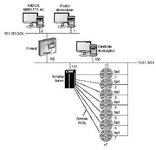
There won't be serial interfaces, and I don't think it will make any difference in the lab since we don't run Non Broadcast Multiple Access over serial such as frame-relay. I'm not sure if PPP features are part of the lab but in Cisco I can run PPP over Ethernet (PPPoE) and I can test the dial-on-demand or PPP authentication feature with it. So using a single dot1q trunk interface for each router and mark the same VLAN number on both routers that need the point-to-point connection should provide us the same output with one physical interface per router for each point-to-point link.
So here are the alternatives for setting up JNCIE Olive lab. I like to use the numbering similar with the options in MPLS inter-AS. And just like in inter-AS, option 3 below is the most interesting :))
JNCIE Lab Option 1: 1 PC for 1 router, multiple NICs
I have a friend who has passed JNCIE with this way. So he bought many used and obsolete PCs, it's old Pentium and but good enough to run FreeBSD with JunOS. Since it was cheap for him to purchase multiple NIC cards, he followed the topology by using direct ethernet point-to-point link even he must provide 6 ethernet ports for some of the PCs. He said all features required in the lab work when running JunOS directly on FreeBSD (no vmware or qemu). So this option is the most straight-fotward and proven to work (he passed, right?) and it doesn't require a switch since each PC will connect directly to each other (except for R1,R2 and P1 in the drawing above that can be connected using cheap hub).
JNCIE Lab Option 2: 1 PC for 1 router, 1 NIC
Similar with option 1 but using only 1 NIC for each PC. As I mentioned above, we should be able to use only a single NIC for each PC by make it as dot1q trunk and put the same VLAN ID on the logical interface for two routers that need to talk to each other. So we need to connect all the routers to a switch. You may want to use Cisco switch since Juniper has not shipped their switch yet heheh
JNCIE Lab Option 3a: 1 PC with Qemu, multiple instances
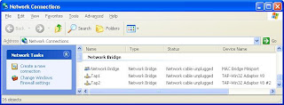
In this world, people always try to find the better way, and cheaper way, to achieve the goal. So why bother to buy multiple PCs if we can run JunOS using qemu with virtual Tap interfaces? So the idea is to run multiple Olive with qemu, and assign one Tap interface to each instance. Then we need to make sure all the interfaces are connected to one virtual switch, in Windows it's called Network Bridge.
So after we create multiple Tap interfaces in Windows using Step 2 in my previous post, we need to put all of them into the bridge in Windows Networking Setup. Just right click the interface and select "Add to Bridge" you should see it will be moved under Network Bridge.
Then when we start qemu, or jqemu, assign the interface into a single VLAN ID. The idea is to have all interfaces in a single VLAN, then later on the separation between each point-to-point link is done in JunOS logical interface configuration with dot1q and unique VLAN ID per link.
Note: I found out that I'm not able to launch multiple qemu instances in Windows if I try to execute it from a single folder. So what I did I create multiple folders and launch Olive from each.
Example, Olive instance 1 is launched with this option:
C:\qemu> jqemu.exe -L . -m 64 -hda Olive.img -serial telnet::1001,server -kernel-kqemu -localtime -net nic,vlan=1,macaddr=00:aa:00:00:01:01,model=i82559er -net tap,vlan=1,ifname=Tap1
Then the 2nd instance is launched from another folder with the next Tap interface but same VLAN option as previous:
C:\qemu2> jqemu.exe -L . -m 64 -hda Olive.img -serial telnet::1002,server -kernel-kqemu -localtime -net nic,vlan=1,macaddr=00:aa:00:00:02:02,model=i82559er -net tap,vlan=1,ifname=Tap2
Two Qemu windows will pop up and obviously we need another 2 DOS prompts to telnet to localhost port 1001 and 1002 to access our Olives. Once we login to Olive, both will have interface fxp0 and let's say we configure 10.1.1.0/30 for both interfaces without logical interface first, just to test the connection:
[edit]
root# edit interfaces fxp0 unit 0 family inet address 10.1.1.1/30
After we commit the changes we should be able to ping each other:
[edit]
root# run ping 10.1.1.2
PING 10.1.1.2 (10.1.1.2): 56 data bytes
64 bytes from 10.1.1.2: icmp_seq=0 ttl=64 time=1.937 ms
64 bytes from 10.1.1.2: icmp_seq=1 ttl=64 time=0.843 ms
This means the bridging between 2 Tap interfaces in Windows networking is working. Now we can create logical interface (unit) and assign different VLAN ID. We must enable vlan-tagging (dot1q) first then let's create VLAN 20 with 20.1.1.0/30 and VLAN 30 with 30.1.1.0/30. Remove the previously configured unit 0 logical interface since it's not tagged.
[edit]
root# delete interfaces fxp0 unit 0
[edit]
root# set interfaces fxp0 vlan-tagging
[edit]
root# set interfaces fxp0 unit 20 vlan-id 20 family inet address 20.1.1.1/30
[edit]
root# set interfaces fxp0 unit 30 vlan-id 30 family inet address 30.1.1.1/30
[edit]
root# run show configuration interfaces
fxp0 {
vlan-tagging;
unit 20 {
vlan-id 20;
family inet {
address 20.1.1.1/30;
}
}
unit 30 {
vlan-id 30;
family inet {
address 30.1.1.1/30;
}
}
}
Once we commit the changes, we should be able to ping both network address. So those are our 2 point-to-point links between 2 routers. Now, let's run OSPF routing area 0 between VLAN 20.
[edit]
root# set protocols ospf area 0.0.0.0 interface fxp0.20 interface-type p2p
root# run show ospf interface
Interface State Area DR ID BDR ID Nbrs
fxp0.20 PtToPt 0.0.0.0 0.0.0.0 0.0.0.0 1
root# run show ospf neighbor
Address Interface State ID Pri Dead
20.1.1.2 fxp0.20 Full 20.1.1.2 128 32
Let's create loopback interface with 100.1.1.1/32 on the first router and 100.1.1.2/32 on the second router and advertise this into OSPF area 0 for testing.
[edit]
root# set interfaces lo0 unit 0 family inet address 100.1.1.1/32
[edit]
root# set protocols ospf area 0.0.0.0 interface lo0 passive
After commit, we should be able to see this route is learned as intra-area:
[edit]
root# run show ospf route
Prefix Path Route NH Metric NextHop Nexthop
Type Type Type Interface addr/label
100.1.1.2 Intra Router IP 1 fxp0.20 20.1.1.2
20.1.1.0/30 Intra Network IP 1 fxp0.20
100.1.1.1/32 Intra Network IP 0 lo0.0
100.1.1.2/32 Intra Network IP 1 fxp0.20 20.1.1.2
We can even try to move the loopback interface to different area just to verify the OSPF:
[edit]
root@Jrocks# delete protocols ospf area 0 interface lo0.0
[edit]
root@Jrocks# set protocols ospf area 1 interface lo0.0 passive
You can see now the peer router loopback address is learned as inter-area:
root# run show ospf route
Prefix Path Route NH Metric NextHop Nexthop
Type Type Type Interface addr/label
100.1.1.2 Intra Area BR IP 1 fxp0.20 20.1.1.2
20.1.1.0/30 Intra Network IP 1 fxp0.20
100.1.1.1/32 Intra Network IP 0 lo0.0
100.1.1.2/32 Inter Network IP 1 fxp0.20 20.1.1.2
Now let's put the interface of VLAN 30 into OSPF area 1
[edit]
root# set protocols ospf area 1 interface fxp0.30 interface-type p2p
As you can see now we have established 2 OSPF neighbors:
[edit]
root# run show ospf neighbor
Address Interface State ID Pri Dead
20.1.1.2 fxp0.20 Full 100.1.1.2 128 34
30.1.1.2 fxp0.30 Full 100.1.1.2 128 31
And if you check the routing table, obviously the 100.1.1.2/32 now is learned as intra-area route again:
root# run show ospf route
Prefix Path Route NH Metric NextHop Nexthop
Type Type Type Interface addr/label
100.1.1.2 Intra Area BR IP 1 fxp0.30 30.1.1.2
20.1.1.0/30 Intra Network IP 1 fxp0.20
30.1.1.0/30 Intra Network IP 1 fxp0.30
100.1.1.1/32 Intra Network IP 0 lo0.0
100.1.1.2/32 Intra Network IP 1 fxp0.30 30.1.1.2
Note: Some people sent me email saying they can't run multicast with qemu. I haven't tested PIM or other multicast protocols but when I changed the OSPF type in VLAN 30 to broadcast, by not using the point-to-point interface type option, I can form neighborship:
[edit]
root# run show ospf neighbor detail
Address Interface State ID Pri Dead
20.1.1.2 fxp0.20 Full 100.1.1.2 128 34
Area 0.0.0.0, opt 0x42, DR 0.0.0.0, BDR 0.0.0.0
Up 00:19:23, adjacent 00:19:23
30.1.1.2 fxp0.30 Full 100.1.1.2 128 39
Area 0.0.0.1, opt 0x42, DR 30.1.1.2, BDR 30.1.1.1
Up 00:01:25, adjacent 00:00:42
[edit]
root# run show ospf interface detail
Interface State Area DR ID BDR ID Nbrs
fxp0.20 PtToPt 0.0.0.0 0.0.0.0 0.0.0.0 1
Type: P2P, Address: 20.1.1.1, Mask: 255.255.255.252, MTU: 1496, Cost: 1
Adj count: 1
Hello: 10, Dead: 40, ReXmit: 5, Not Stub
Auth type: None
fxp0.30 BDR 0.0.0.1 100.1.1.2 100.1.1.1 1
Type: LAN, Address: 30.1.1.1, Mask: 255.255.255.252, MTU: 1496, Cost: 1
DR addr: 30.1.1.2, BDR addr: 30.1.1.1, Adj count: 1, Priority: 128
Hello: 10, Dead: 40, ReXmit: 5, Not Stub
Auth type: None
I tried to configure RIP as well and it works too. So I guess multicast-based protocol should work, but please let me know if you find it otherwise.
JNCIE Lab Option 3b: 1 PC with Qemu, single instances
So you think making multiple folders is not good enough for you? You don't like the previous option since you must allocate memory for each instance? Alright, here is another option that I got from my Chinese friend who's been helping me setting this up: Running only a single Qemu instance but with logical router feature inside JunOS. And each logical router will take one fxp interface, or one Tap interface if you see it from Windows point of view.
So when we start Olive, assign multiple TAP interfaces into this instance. Each logical router will take one fxp interface.
C:\qemu>jqemu.exe -L . -m 192 -hda Olive.img -serial telnet::1001,server -kernel-kqemu -localtime -net nic,vlan=1,macaddr=00:aa:00:00:01:01,model=i82559er -net tap,vlan=1,ifname=Tap1 -net nic,vlan=1,macaddr=00:aa:00:00:02:02,model=i82559er -net tap,vlan=1,ifname=Tap2
Once we are inside Olive, create logical router R1 and R2, then enable vlan-tagging on both fxp0 and fxp1 interfaces.
[edit]
root# set logical-routers R1
[edit]
root# set logical-routers R2
[edit]
root# set interfaces fxp0 vlan-tagging
[edit]
root# set interfaces fxp1 vlan-tagging
Assign IP address and VLAN ID just like how we did in Option 3a, but this time we have to specify the logical router name. Logical-router R1 will use fxp0 while logical-router R2 will use fxp1:
[edit]
root# set logical-router R1 interfaces fxp0 unit 20 vlan-id 20 family inet address 20.1.1.1/30
[edit]
root# set logical-router R1 interfaces fxp0 unit 30 vlan-id 30 family inet address 30.1.1.1/30
[edit]
root# set logical-router R2 interfaces fxp1 unit 20 vlan-id 20 family inet address 20.1.1.2/30
[edit]
root# set logical-router R2 interfaces fxp1 unit 30 vlan-id 30 family inet address 30.1.1.2/30
[edit]
root# run show configuration logical-routers R1
interfaces {
fxp0 {
unit 20 {
vlan-id 20;
family inet {
address 20.1.1.1/30;
}
}
unit 30 {
vlan-id 30;
family inet {
address 30.1.1.1/30;
}
}
}
}
[edit]
root# run show configuration logical-routers R2
interfaces {
fxp1 {
unit 20 {
vlan-id 20;
family inet {
address 20.1.1.2/30;
}
}
unit 30 {
vlan-id 30;
family inet {
address 30.1.1.2/30;
}
}
}
}
When we want to run ping test, specify the logical router name as the source of the ping packet:
[edit]
root# run ping logical-router R1 20.1.1.2
PING 20.1.1.2 (20.1.1.2): 56 data bytes
64 bytes from 20.1.1.2: icmp_seq=0 ttl=64 time=3.010 ms
64 bytes from 20.1.1.2: icmp_seq=1 ttl=64 time=0.453 ms
Configure OSPF Area 0 for VLAN 20:
[edit]
root# set logical-routers R1 interfaces lo0.0 family inet address 100.1.1.1/32
[edit]
root# set logical-routers R2 interfaces lo0.1 family inet address 100.1.1.2/32
[edit]
root# set logical-routers R1 protocols ospf area 0 interface fxp0.20
[edit]
root# set logical-routers R2 protocols ospf area 0 interface fxp1.20
Check the OSPF status and routes:
[edit]
root# run show ospf neighbor logical-router R1
Address Interface State ID Pri Dead
20.1.1.2 fxp0.20 Full 100.1.1.2 128 37
[edit]
root# run show ospf route logical-router R1
Prefix Path Route NH Metric NextHop Nexthop
Type Type Type Interface addr/label
100.1.1.2 Intra Router IP 1 fxp0.20 20.1.1.2
20.1.1.0/30 Intra Network IP 1 fxp0.20
100.1.1.2/32 Intra Network IP 1 fxp0.20 20.1.1.2
Ping R2 loopback address from R1:
root# run ping logical-router R1 100.1.1.2
PING 100.1.1.2 (100.1.1.2): 56 data bytes
64 bytes from 100.1.1.2: icmp_seq=0 ttl=64 time=0.725 ms
64 bytes from 100.1.1.2: icmp_seq=1 ttl=64 time=0.467 ms
Just for fun, put the other logical interface into OSPF Area 1:
[edit]
root# set logical-routers R1 protocols ospf area 1 interface fxp0.30 interface-type p2p
[edit]
root# set logical-routers R2 protocols ospf area 1 interface fxp1.30 interface-type p2p
[edit]
root# run show ospf neighbor logical-router R1 detail
Address Interface State ID Pri Dead
20.1.1.2 fxp0.20 Full 100.1.1.2 128 35
Area 0.0.0.0, opt 0x42, DR 20.1.1.1, BDR 20.1.1.2
Up 00:01:54, adjacent 00:01:54
30.1.1.2 fxp0.30 Full 100.1.1.2 128 35
Area 0.0.0.1, opt 0x42, DR 0.0.0.0, BDR 0.0.0.0
Up 00:00:05, adjacent 00:00:05
[edit]
root# run show ospf interface logical-router R1 detail
Interface State Area DR ID BDR ID Nbrs
fxp0.20 DR 0.0.0.0 100.1.1.1 100.1.1.2 1
Type: LAN, Address: 20.1.1.1, Mask: 255.255.255.252, MTU: 1496, Cost: 1
DR addr: 20.1.1.1, BDR addr: 20.1.1.2, Adj count: 1, Priority: 128
Hello: 10, Dead: 40, ReXmit: 5, Not Stub
Auth type: None
fxp0.30 PtToPt 0.0.0.1 0.0.0.0 0.0.0.0 1
Type: P2P, Address: 30.1.1.1, Mask: 255.255.255.252, MTU: 1496, Cost: 1
Adj count: 1
Hello: 10, Dead: 40, ReXmit: 5, Not Stub
Auth type: None
As you can see, the way to configure Option 3b with logical router is the same with Option 3a except now for all configuration or show command we must specify the logical router name as well.
JNCIE Lab Option 3c: Combination
Option 3c is just combination of all previous options. Use your imagination! The following might give you some idea:
- 1 PC running Olive, without qemu, with multiple NICs to connect to a switch. Then run logical routers and assign 1 NIC to each logical router, and just as Option 3b enable dot1q and use logical interfaces on each logical router.
- 2 PCs or more running Olive, with multiple qemu instances and multiple NICs on each PC to connect to a switch. Then each qemu can take 1 NIC, use dot1q with logical interfaces but no logical router is required. This might be a good case if you have few PCs and each has multiple NICs and able to run only several qemu instances.
- 2 PCs or more running Olive with single qemu instance on each PC, and with single NIC on each PC to connect to a switch. Then in Olive on each PC create logical routers to share that single NIC. To make it easy make sure logical routers in the same Olive are not required to talk to each other, so only to another logical routers in different PC. Obviously that NIC must be configured as dot1q and each logical router will use logical interfaces.
To make it even more granular, we can combine real NICs with TAP interfaces! So if we have 2 PCs or more with single NIC on each PC, 1 PC can run multiple qemu instances, and within 1 PC they communicate each other using TAP interfaces but those qemu instances can connect to another qemu in different PC using real NIC.
And one more thing, actually we can setup point-to-point connection between 2 qemu instances, or between 2 logical routers within 1 Olive/qemu using socket or UDP port! So for UDP, for example, we need to specify the source and destination port in -net option when we define the interface:
C:\qemu> jqemu.exe -L . -m 192 -hda Olive.img -serial telnet::1001,server -kernel-kqemu -localtime -net nic,vlan=1,macaddr=00:aa:00:00:01:01,model=i82559er -net udp,vlan=1,sport=10001,dport=10002,daddr=127.0.0.1 -net nic,vlan=1,macaddr=00:aa:00:00:02:02,model=i82559er -net udp,vlan=1,sport=10002,dport=10001,daddr=127.0.0.1
Sky is the limit!
As I mentioned in the beginning, I haven't started the journey yet so I don't know if all features in the lab can be tested with Olive, especially the option to use qemu multiple instances or qemu single instance with logical routers. So appreciate if you have already tried those options to provide your feedback. Thanks.
Now it's time to go back to IOS XR ;)
This topology drawing is taken from JNCIE study guide.

As you can see, there are 7 core routers in the middle, 4 routers for external AS, and 1 router called Data Center. Most of the links are point-to-point. Knowing this fact, I believe we just need 1 ethernet interface (2 if you want OOB) for each router and we should be able to use logical interface with dot1q trunk and VLAN tagging to distinguish one point-to-point link with the others. So it will look like as the next drawing taken from the same book:

There won't be serial interfaces, and I don't think it will make any difference in the lab since we don't run Non Broadcast Multiple Access over serial such as frame-relay. I'm not sure if PPP features are part of the lab but in Cisco I can run PPP over Ethernet (PPPoE) and I can test the dial-on-demand or PPP authentication feature with it. So using a single dot1q trunk interface for each router and mark the same VLAN number on both routers that need the point-to-point connection should provide us the same output with one physical interface per router for each point-to-point link.
So here are the alternatives for setting up JNCIE Olive lab. I like to use the numbering similar with the options in MPLS inter-AS. And just like in inter-AS, option 3 below is the most interesting :))
JNCIE Lab Option 1: 1 PC for 1 router, multiple NICs
I have a friend who has passed JNCIE with this way. So he bought many used and obsolete PCs, it's old Pentium and but good enough to run FreeBSD with JunOS. Since it was cheap for him to purchase multiple NIC cards, he followed the topology by using direct ethernet point-to-point link even he must provide 6 ethernet ports for some of the PCs. He said all features required in the lab work when running JunOS directly on FreeBSD (no vmware or qemu). So this option is the most straight-fotward and proven to work (he passed, right?) and it doesn't require a switch since each PC will connect directly to each other (except for R1,R2 and P1 in the drawing above that can be connected using cheap hub).
JNCIE Lab Option 2: 1 PC for 1 router, 1 NIC
Similar with option 1 but using only 1 NIC for each PC. As I mentioned above, we should be able to use only a single NIC for each PC by make it as dot1q trunk and put the same VLAN ID on the logical interface for two routers that need to talk to each other. So we need to connect all the routers to a switch. You may want to use Cisco switch since Juniper has not shipped their switch yet heheh
JNCIE Lab Option 3a: 1 PC with Qemu, multiple instances
In this world, people always try to find the better way, and cheaper way, to achieve the goal. So why bother to buy multiple PCs if we can run JunOS using qemu with virtual Tap interfaces? So the idea is to run multiple Olive with qemu, and assign one Tap interface to each instance. Then we need to make sure all the interfaces are connected to one virtual switch, in Windows it's called Network Bridge.
So after we create multiple Tap interfaces in Windows using Step 2 in my previous post, we need to put all of them into the bridge in Windows Networking Setup. Just right click the interface and select "Add to Bridge" you should see it will be moved under Network Bridge.

Then when we start qemu, or jqemu, assign the interface into a single VLAN ID. The idea is to have all interfaces in a single VLAN, then later on the separation between each point-to-point link is done in JunOS logical interface configuration with dot1q and unique VLAN ID per link.
Note: I found out that I'm not able to launch multiple qemu instances in Windows if I try to execute it from a single folder. So what I did I create multiple folders and launch Olive from each.
Example, Olive instance 1 is launched with this option:
C:\qemu> jqemu.exe -L . -m 64 -hda Olive.img -serial telnet::1001,server -kernel-kqemu -localtime -net nic,vlan=1,macaddr=00:aa:00:00:01:01,model=i82559er -net tap,vlan=1,ifname=Tap1
Then the 2nd instance is launched from another folder with the next Tap interface but same VLAN option as previous:
C:\qemu2> jqemu.exe -L . -m 64 -hda Olive.img -serial telnet::1002,server -kernel-kqemu -localtime -net nic,vlan=1,macaddr=00:aa:00:00:02:02,model=i82559er -net tap,vlan=1,ifname=Tap2
Two Qemu windows will pop up and obviously we need another 2 DOS prompts to telnet to localhost port 1001 and 1002 to access our Olives. Once we login to Olive, both will have interface fxp0 and let's say we configure 10.1.1.0/30 for both interfaces without logical interface first, just to test the connection:
[edit]
root# edit interfaces fxp0 unit 0 family inet address 10.1.1.1/30
After we commit the changes we should be able to ping each other:
[edit]
root# run ping 10.1.1.2
PING 10.1.1.2 (10.1.1.2): 56 data bytes
64 bytes from 10.1.1.2: icmp_seq=0 ttl=64 time=1.937 ms
64 bytes from 10.1.1.2: icmp_seq=1 ttl=64 time=0.843 ms
This means the bridging between 2 Tap interfaces in Windows networking is working. Now we can create logical interface (unit) and assign different VLAN ID. We must enable vlan-tagging (dot1q) first then let's create VLAN 20 with 20.1.1.0/30 and VLAN 30 with 30.1.1.0/30. Remove the previously configured unit 0 logical interface since it's not tagged.
[edit]
root# delete interfaces fxp0 unit 0
[edit]
root# set interfaces fxp0 vlan-tagging
[edit]
root# set interfaces fxp0 unit 20 vlan-id 20 family inet address 20.1.1.1/30
[edit]
root# set interfaces fxp0 unit 30 vlan-id 30 family inet address 30.1.1.1/30
[edit]
root# run show configuration interfaces
fxp0 {
vlan-tagging;
unit 20 {
vlan-id 20;
family inet {
address 20.1.1.1/30;
}
}
unit 30 {
vlan-id 30;
family inet {
address 30.1.1.1/30;
}
}
}
Once we commit the changes, we should be able to ping both network address. So those are our 2 point-to-point links between 2 routers. Now, let's run OSPF routing area 0 between VLAN 20.
[edit]
root# set protocols ospf area 0.0.0.0 interface fxp0.20 interface-type p2p
root# run show ospf interface
Interface State Area DR ID BDR ID Nbrs
fxp0.20 PtToPt 0.0.0.0 0.0.0.0 0.0.0.0 1
root# run show ospf neighbor
Address Interface State ID Pri Dead
20.1.1.2 fxp0.20 Full 20.1.1.2 128 32
Let's create loopback interface with 100.1.1.1/32 on the first router and 100.1.1.2/32 on the second router and advertise this into OSPF area 0 for testing.
[edit]
root# set interfaces lo0 unit 0 family inet address 100.1.1.1/32
[edit]
root# set protocols ospf area 0.0.0.0 interface lo0 passive
After commit, we should be able to see this route is learned as intra-area:
[edit]
root# run show ospf route
Prefix Path Route NH Metric NextHop Nexthop
Type Type Type Interface addr/label
100.1.1.2 Intra Router IP 1 fxp0.20 20.1.1.2
20.1.1.0/30 Intra Network IP 1 fxp0.20
100.1.1.1/32 Intra Network IP 0 lo0.0
100.1.1.2/32 Intra Network IP 1 fxp0.20 20.1.1.2
We can even try to move the loopback interface to different area just to verify the OSPF:
[edit]
root@Jrocks# delete protocols ospf area 0 interface lo0.0
[edit]
root@Jrocks# set protocols ospf area 1 interface lo0.0 passive
You can see now the peer router loopback address is learned as inter-area:
root# run show ospf route
Prefix Path Route NH Metric NextHop Nexthop
Type Type Type Interface addr/label
100.1.1.2 Intra Area BR IP 1 fxp0.20 20.1.1.2
20.1.1.0/30 Intra Network IP 1 fxp0.20
100.1.1.1/32 Intra Network IP 0 lo0.0
100.1.1.2/32 Inter Network IP 1 fxp0.20 20.1.1.2
Now let's put the interface of VLAN 30 into OSPF area 1
[edit]
root# set protocols ospf area 1 interface fxp0.30 interface-type p2p
As you can see now we have established 2 OSPF neighbors:
[edit]
root# run show ospf neighbor
Address Interface State ID Pri Dead
20.1.1.2 fxp0.20 Full 100.1.1.2 128 34
30.1.1.2 fxp0.30 Full 100.1.1.2 128 31
And if you check the routing table, obviously the 100.1.1.2/32 now is learned as intra-area route again:
root# run show ospf route
Prefix Path Route NH Metric NextHop Nexthop
Type Type Type Interface addr/label
100.1.1.2 Intra Area BR IP 1 fxp0.30 30.1.1.2
20.1.1.0/30 Intra Network IP 1 fxp0.20
30.1.1.0/30 Intra Network IP 1 fxp0.30
100.1.1.1/32 Intra Network IP 0 lo0.0
100.1.1.2/32 Intra Network IP 1 fxp0.30 30.1.1.2
Note: Some people sent me email saying they can't run multicast with qemu. I haven't tested PIM or other multicast protocols but when I changed the OSPF type in VLAN 30 to broadcast, by not using the point-to-point interface type option, I can form neighborship:
[edit]
root# run show ospf neighbor detail
Address Interface State ID Pri Dead
20.1.1.2 fxp0.20 Full 100.1.1.2 128 34
Area 0.0.0.0, opt 0x42, DR 0.0.0.0, BDR 0.0.0.0
Up 00:19:23, adjacent 00:19:23
30.1.1.2 fxp0.30 Full 100.1.1.2 128 39
Area 0.0.0.1, opt 0x42, DR 30.1.1.2, BDR 30.1.1.1
Up 00:01:25, adjacent 00:00:42
[edit]
root# run show ospf interface detail
Interface State Area DR ID BDR ID Nbrs
fxp0.20 PtToPt 0.0.0.0 0.0.0.0 0.0.0.0 1
Type: P2P, Address: 20.1.1.1, Mask: 255.255.255.252, MTU: 1496, Cost: 1
Adj count: 1
Hello: 10, Dead: 40, ReXmit: 5, Not Stub
Auth type: None
fxp0.30 BDR 0.0.0.1 100.1.1.2 100.1.1.1 1
Type: LAN, Address: 30.1.1.1, Mask: 255.255.255.252, MTU: 1496, Cost: 1
DR addr: 30.1.1.2, BDR addr: 30.1.1.1, Adj count: 1, Priority: 128
Hello: 10, Dead: 40, ReXmit: 5, Not Stub
Auth type: None
I tried to configure RIP as well and it works too. So I guess multicast-based protocol should work, but please let me know if you find it otherwise.
JNCIE Lab Option 3b: 1 PC with Qemu, single instances
So you think making multiple folders is not good enough for you? You don't like the previous option since you must allocate memory for each instance? Alright, here is another option that I got from my Chinese friend who's been helping me setting this up: Running only a single Qemu instance but with logical router feature inside JunOS. And each logical router will take one fxp interface, or one Tap interface if you see it from Windows point of view.
So when we start Olive, assign multiple TAP interfaces into this instance. Each logical router will take one fxp interface.
C:\qemu>jqemu.exe -L . -m 192 -hda Olive.img -serial telnet::1001,server -kernel-kqemu -localtime -net nic,vlan=1,macaddr=00:aa:00:00:01:01,model=i82559er -net tap,vlan=1,ifname=Tap1 -net nic,vlan=1,macaddr=00:aa:00:00:02:02,model=i82559er -net tap,vlan=1,ifname=Tap2
Once we are inside Olive, create logical router R1 and R2, then enable vlan-tagging on both fxp0 and fxp1 interfaces.
[edit]
root# set logical-routers R1
[edit]
root# set logical-routers R2
[edit]
root# set interfaces fxp0 vlan-tagging
[edit]
root# set interfaces fxp1 vlan-tagging
Assign IP address and VLAN ID just like how we did in Option 3a, but this time we have to specify the logical router name. Logical-router R1 will use fxp0 while logical-router R2 will use fxp1:
[edit]
root# set logical-router R1 interfaces fxp0 unit 20 vlan-id 20 family inet address 20.1.1.1/30
[edit]
root# set logical-router R1 interfaces fxp0 unit 30 vlan-id 30 family inet address 30.1.1.1/30
[edit]
root# set logical-router R2 interfaces fxp1 unit 20 vlan-id 20 family inet address 20.1.1.2/30
[edit]
root# set logical-router R2 interfaces fxp1 unit 30 vlan-id 30 family inet address 30.1.1.2/30
[edit]
root# run show configuration logical-routers R1
interfaces {
fxp0 {
unit 20 {
vlan-id 20;
family inet {
address 20.1.1.1/30;
}
}
unit 30 {
vlan-id 30;
family inet {
address 30.1.1.1/30;
}
}
}
}
[edit]
root# run show configuration logical-routers R2
interfaces {
fxp1 {
unit 20 {
vlan-id 20;
family inet {
address 20.1.1.2/30;
}
}
unit 30 {
vlan-id 30;
family inet {
address 30.1.1.2/30;
}
}
}
}
When we want to run ping test, specify the logical router name as the source of the ping packet:
[edit]
root# run ping logical-router R1 20.1.1.2
PING 20.1.1.2 (20.1.1.2): 56 data bytes
64 bytes from 20.1.1.2: icmp_seq=0 ttl=64 time=3.010 ms
64 bytes from 20.1.1.2: icmp_seq=1 ttl=64 time=0.453 ms
Configure OSPF Area 0 for VLAN 20:
[edit]
root# set logical-routers R1 interfaces lo0.0 family inet address 100.1.1.1/32
[edit]
root# set logical-routers R2 interfaces lo0.1 family inet address 100.1.1.2/32
[edit]
root# set logical-routers R1 protocols ospf area 0 interface fxp0.20
[edit]
root# set logical-routers R2 protocols ospf area 0 interface fxp1.20
Check the OSPF status and routes:
[edit]
root# run show ospf neighbor logical-router R1
Address Interface State ID Pri Dead
20.1.1.2 fxp0.20 Full 100.1.1.2 128 37
[edit]
root# run show ospf route logical-router R1
Prefix Path Route NH Metric NextHop Nexthop
Type Type Type Interface addr/label
100.1.1.2 Intra Router IP 1 fxp0.20 20.1.1.2
20.1.1.0/30 Intra Network IP 1 fxp0.20
100.1.1.2/32 Intra Network IP 1 fxp0.20 20.1.1.2
Ping R2 loopback address from R1:
root# run ping logical-router R1 100.1.1.2
PING 100.1.1.2 (100.1.1.2): 56 data bytes
64 bytes from 100.1.1.2: icmp_seq=0 ttl=64 time=0.725 ms
64 bytes from 100.1.1.2: icmp_seq=1 ttl=64 time=0.467 ms
Just for fun, put the other logical interface into OSPF Area 1:
[edit]
root# set logical-routers R1 protocols ospf area 1 interface fxp0.30 interface-type p2p
[edit]
root# set logical-routers R2 protocols ospf area 1 interface fxp1.30 interface-type p2p
[edit]
root# run show ospf neighbor logical-router R1 detail
Address Interface State ID Pri Dead
20.1.1.2 fxp0.20 Full 100.1.1.2 128 35
Area 0.0.0.0, opt 0x42, DR 20.1.1.1, BDR 20.1.1.2
Up 00:01:54, adjacent 00:01:54
30.1.1.2 fxp0.30 Full 100.1.1.2 128 35
Area 0.0.0.1, opt 0x42, DR 0.0.0.0, BDR 0.0.0.0
Up 00:00:05, adjacent 00:00:05
[edit]
root# run show ospf interface logical-router R1 detail
Interface State Area DR ID BDR ID Nbrs
fxp0.20 DR 0.0.0.0 100.1.1.1 100.1.1.2 1
Type: LAN, Address: 20.1.1.1, Mask: 255.255.255.252, MTU: 1496, Cost: 1
DR addr: 20.1.1.1, BDR addr: 20.1.1.2, Adj count: 1, Priority: 128
Hello: 10, Dead: 40, ReXmit: 5, Not Stub
Auth type: None
fxp0.30 PtToPt 0.0.0.1 0.0.0.0 0.0.0.0 1
Type: P2P, Address: 30.1.1.1, Mask: 255.255.255.252, MTU: 1496, Cost: 1
Adj count: 1
Hello: 10, Dead: 40, ReXmit: 5, Not Stub
Auth type: None
As you can see, the way to configure Option 3b with logical router is the same with Option 3a except now for all configuration or show command we must specify the logical router name as well.
JNCIE Lab Option 3c: Combination
Option 3c is just combination of all previous options. Use your imagination! The following might give you some idea:
- 1 PC running Olive, without qemu, with multiple NICs to connect to a switch. Then run logical routers and assign 1 NIC to each logical router, and just as Option 3b enable dot1q and use logical interfaces on each logical router.
- 2 PCs or more running Olive, with multiple qemu instances and multiple NICs on each PC to connect to a switch. Then each qemu can take 1 NIC, use dot1q with logical interfaces but no logical router is required. This might be a good case if you have few PCs and each has multiple NICs and able to run only several qemu instances.
- 2 PCs or more running Olive with single qemu instance on each PC, and with single NIC on each PC to connect to a switch. Then in Olive on each PC create logical routers to share that single NIC. To make it easy make sure logical routers in the same Olive are not required to talk to each other, so only to another logical routers in different PC. Obviously that NIC must be configured as dot1q and each logical router will use logical interfaces.
To make it even more granular, we can combine real NICs with TAP interfaces! So if we have 2 PCs or more with single NIC on each PC, 1 PC can run multiple qemu instances, and within 1 PC they communicate each other using TAP interfaces but those qemu instances can connect to another qemu in different PC using real NIC.
And one more thing, actually we can setup point-to-point connection between 2 qemu instances, or between 2 logical routers within 1 Olive/qemu using socket or UDP port! So for UDP, for example, we need to specify the source and destination port in -net option when we define the interface:
C:\qemu> jqemu.exe -L . -m 192 -hda Olive.img -serial telnet::1001,server -kernel-kqemu -localtime -net nic,vlan=1,macaddr=00:aa:00:00:01:01,model=i82559er -net udp,vlan=1,sport=10001,dport=10002,daddr=127.0.0.1 -net nic,vlan=1,macaddr=00:aa:00:00:02:02,model=i82559er -net udp,vlan=1,sport=10002,dport=10001,daddr=127.0.0.1
Sky is the limit!
As I mentioned in the beginning, I haven't started the journey yet so I don't know if all features in the lab can be tested with Olive, especially the option to use qemu multiple instances or qemu single instance with logical routers. So appreciate if you have already tried those options to provide your feedback. Thanks.
Now it's time to go back to IOS XR ;)
posted by Himawan Nugroho at 3:10 PM 17 comments ![]()
Sunday, January 20, 2008
Olive is Alive
I was bored and my Survival Mode level was high, so I started looking at my targets. The last 3 pictures in the right can be achieved easier if I can get the first 3 pictures in the left. Since the 1st target depends on the projects that my team are asked to deliver, so I moved to the 2nd one.
Many have asked me why I want to do another certification. And few even said I'm crazy to take certification from my company's competitor. My reply was "I need to refresh my skill and it's better to geeking out in the lab instead of doing nothing". Some may understand and some may not, but I don't want to get into a lengthy discussion and long debate. I simply want to do it. And I will do it.
I guess I have been influenced by Paul Arden: Whatever you think, think the opposite.
I know people may against this idea and call me a bit insane. And I won't get any support from my company. So far I have not found any workbooks available for this lab certification. I consider this journey will be more difficult than my CCIEs, but that's what make it more interesting. JNCIE will force me to re-learn SP technologies from different perspective not only from my company's. And for me JunOS CLI is just another interface to test and implement the concept, such as normal IOS CLI or XR.
My first step on this target is to prepare the emulation so I can practice JunOS. My research made me meet Olive, a name given to JunOS running on a PC.
Before I continue, let's go through some disclaimers:
Disclaimer 1: Olive doesn't exist.
Read the secrecy of Olive from this site.
Disclaimer 2: Whatever I'm doing with Olive has nothing to do with my work. Cisco never asked me to do a research about this emulator nor they ever asked me to do any integration testing between JunOS and IOS using emulator.
Disclaimer 3: Don't ask me to provide JunOS, or even Cisco IOS for dynamips (yes I received some requests through email). If you are really serious about doing this kind of stuff, you should have already known from where you can get all the resources.
Basically most information I put in here are available from these 2 sites: Juniper Clue and Internetwork Pro, with some addition from my own research, my Chinese friends and google to translate some Chinese websites.
So here are the steps to bring Olive to life. I'm doing it on Windows XP since that's the only OS in the laptop that I carry wherever I go, and the whole idea is to make it easier for me to practice the lab anytime, anywhere. I'm using Qemu and install FreeBSD on it, then I can install JunOS on that FreeBSD.
1. Download the latest version of Qemu for Windows.
Qemu website is in here. And Qemu for Windows can be downloaded from here. I'm using qemu 0.9.0. Simply unzip the file into a directory.
2. Download OpenVPN to create TAP interface.
TAP interface is a virtual interface that can be used by JunOS as fxp interface and allowing us to communicate from Windows OS to Olive over the virtual network. I'm using OpenVPN 2.0.9 for Windows. During the installation just select "TAP-Win32 Virtual Ethernet Adapter". We can create several tap interfaces with "Add a new TAP-Win32 virtual ethernet adapter" and rename them with something like 'Tap1', 'Tap2' and so on
3. Download FreeBSD 4.4 mini ISO
JunOS will be installed on top of FreeBSD.
4. Get JunOS. Mine is 8.3R2.8 version.
5. Download modified version of Qemu, Jqemu.
You have to subscribe to the forum in order to download this rar file (hint: use google to translate and locate the file first) and put it in the same folder with Qemu. Jqemu is Qemu version that can provide the driver for virtual intel nic type i82559er.
6. It's time to create the image for FreeBSD/Olive.
Run this command to allocate 3 Gig for the image:
C:\qemu>qemu-img.exe create olive.img -f qcow2 3G
Formating 'olive.img', fmt=qcow2, size=3145728 kB
7. Put the FreeBSD mini ISO in the same Qemu directory, and use this command to boot FreeBSD from the iso.
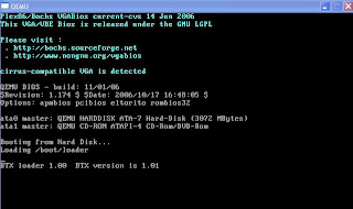
C:\qemu>qemu.exe -L . -m 256 -hda olive.img -cdrom 4.4-mini.iso -boot d -localtime
Qemu window will pop up:
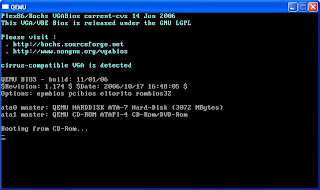
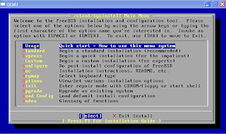
Let Qemu boot the FreeBSD installation image, and just follow the instruction on the menu to do standard installation:
- Skip Kernel configuration
- Choose standard installation
- With fdisk, press A to allocate entire disk for bsd
- Just select: install a standard MBR
- Create partition (with C):
512M for / partition
1024M for swap partition
128M for /config
and the rest for /var
- Choose installation type: user, and select No for FreeBSD ports
- X to Exit the menu and install from CD/DVD
- Wait until it's done
- select No No No No No on all the user confirmation requested (Ethernet/SLIP config, gateway, inetd, FTP, NFS, security, console, linux compatibility, set time, etc)
- X to exit the menu
- No for browse FreeBSD package collection and initial user account
- Type root password
- No for chance to set any last options
- Select 'X' to Exit the installation, it will reboot
- while it's rebooting, exit from Qemu by pressing Ctrl-Alt-2, then type: quit
8. Upload JunOS install package from Windows
Ok, FreeBSD has been installed in the Qemu and we are back to Windows again. Now we need to transfer JunOS file from windows to our BSD, so we need the BSD to have an interface that we can use to transfer the file using the network, for example with FTP.
Let's say we have created 1 Tap interface and rename it as Tap1. Right click this Tap1 interface on Windows Control Panel - Network Connections and give IP address for example 10.1.1.1/8
Start qemu using jqemu, with options to include i82559er as nic type, assigned mac-address and map the nic to interface name Tap1:
C:/qemu>jqemu.exe -L . -m 256 -hda Olive.img -localtime -net nic,vlan=1,macaddr=00:aa:00:00:01:01,model=i82559er -net tap,vlan=1,ifname=Tap1
We need to make sure we can have connectivity between the host Windows with Tap1 interface and the guess FreeBSD with fxp0 interface
- login to the FreeBSD with the root account and password we set during the installation
- setup the IP address
#ifconfig fxp0 up 10.1.1.2
- try to ping 10.1.1.1 from FreeBSD
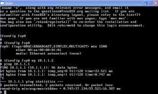
We can use FTP to copy jinstall file from Windows to BSD:
#cd /var/tmp
#ftp 10.1.1.1
Change type to binary and get the jinstall file.
9. Modify jinstall file and install
JunOS image after 7.4 version has a binary called checkpic. This binary will fail and the image cannot be installed. Replacing this binary with /usr/bin/true fixes the issue.
We need to untar the signed jinstall file first:
#cd /var/tmp
#mkdir jinst-signed
#cd jinst-signed
#tar zxvf ../jinstall-8.3R2.8-export-signed.tgz
Then untar the unsigned image:
#mkdir jinst
#cd jinst
#tar zxvf ../jinstall-8.3R2.8-export.tgz
Extract the pkgtools.tgz file and replace the checkpic binary inside with /usr/bin/true :
#mkdir pkgtools
#cd pkgtools
#tar zxvf ../pkgtools.tgz
#cd bin
#cp /usr/bin/true ./checkpic
#cd ..
Create tar for pkgtools then remove the directory:
#tar zcvf ../pkgtools.tgz *
#cd ..
#rm -rf pkgtools
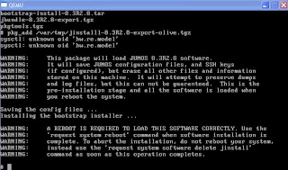
Create tar for the new jinstall package with modified checkpic
#tar zcfv /var/tmp/jinstall-8.3R2.8-export-olive.tgz *
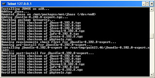
Then install the new jinstall with bsd pkg_add tool:
#pkg_add /var/tmp/jinstall-8.3R2.8-export-olive.tgz
It will ask to reboot to continue the installation.
#reboot
When it's rebooting, press Ctrl-Alt-2 and type: quit.
10. Login to Olive for the first time!
The default behavior from JunOS won't allow us to login to it from the standard output and we must use serial console instead. So start Qemu again using Jqemu.exe and this time put the option to redirect the output to serial port emulated by local TCP port 1001.
C:\qemu>jqemu.exe -L . -m 256 -hda Olive.img -serial telnet::1001,server -localtime -net nic,vlan=1,macaddr=00:aa:00:00:01:01,model=i82559er -net tap,vlan=1,ifname=Tap1
Qemu windows will pop up and it's waiting for TCP connection to port 1001.
Open another Windows DOS prompt and telnet 127.0.0.1 1001.
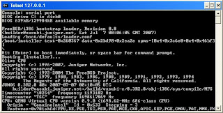
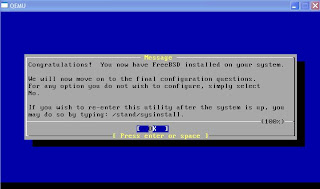
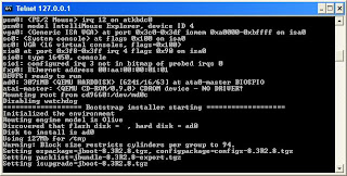
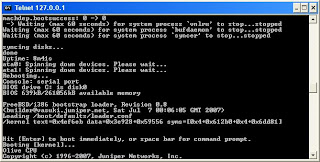
We can see the whole installation process until it reboots when it's done.
After JunOS installation is complete we can login to Olive for the first time with root account and no password.
From BSD prompt, type 'cli' to go to JunOS prompt, then assign the IP address 10.1.1.2/8 to fxp0
root@%cli
root>edit
[edit]
root#
Create password for the root account, then set the IP address
[edit]
root#set system root-authentication plain-text-password
New password:
Retype new password:
[edit]
root#set interface fxp0 unit 0 family inet address 10.1.1.2/8
[edit]
root#commit
commit complete
If everything is set up properly, we should have connectivity from Olive from fxp0 interface to Windows Tap 1 interface.
Later we can install Kqemu to improve the performance:
- download kqemu from here, and extract it to a folder.
- Go to that folder, then the kqemu folder within it, and right click on kqemu.inf, and select install.
- from windows prompt type 'net start kqemu'
C:\>net start kqemu
The KQEMU virtualisation module for QEMU service was started successfully.
Now we can start Olive using Jqemu with additional kernel-kqemu option:
C:\qemu>jqemu.exe -L . -m 256 -hda Olive.img -serial telnet::1001,server -kernel-kqemu -localtime -net nic,vlan=1,macaddr=00:aa:00:00:01:01,model=i82559er -net tap,vlan=1,ifname=Tap1
Many have asked me why I want to do another certification. And few even said I'm crazy to take certification from my company's competitor. My reply was "I need to refresh my skill and it's better to geeking out in the lab instead of doing nothing". Some may understand and some may not, but I don't want to get into a lengthy discussion and long debate. I simply want to do it. And I will do it.
I guess I have been influenced by Paul Arden: Whatever you think, think the opposite.
I know people may against this idea and call me a bit insane. And I won't get any support from my company. So far I have not found any workbooks available for this lab certification. I consider this journey will be more difficult than my CCIEs, but that's what make it more interesting. JNCIE will force me to re-learn SP technologies from different perspective not only from my company's. And for me JunOS CLI is just another interface to test and implement the concept, such as normal IOS CLI or XR.
My first step on this target is to prepare the emulation so I can practice JunOS. My research made me meet Olive, a name given to JunOS running on a PC.
Before I continue, let's go through some disclaimers:
Disclaimer 1: Olive doesn't exist.
Read the secrecy of Olive from this site.
Disclaimer 2: Whatever I'm doing with Olive has nothing to do with my work. Cisco never asked me to do a research about this emulator nor they ever asked me to do any integration testing between JunOS and IOS using emulator.
Disclaimer 3: Don't ask me to provide JunOS, or even Cisco IOS for dynamips (yes I received some requests through email). If you are really serious about doing this kind of stuff, you should have already known from where you can get all the resources.
Basically most information I put in here are available from these 2 sites: Juniper Clue and Internetwork Pro, with some addition from my own research, my Chinese friends and google to translate some Chinese websites.
So here are the steps to bring Olive to life. I'm doing it on Windows XP since that's the only OS in the laptop that I carry wherever I go, and the whole idea is to make it easier for me to practice the lab anytime, anywhere. I'm using Qemu and install FreeBSD on it, then I can install JunOS on that FreeBSD.
1. Download the latest version of Qemu for Windows.
Qemu website is in here. And Qemu for Windows can be downloaded from here. I'm using qemu 0.9.0. Simply unzip the file into a directory.
2. Download OpenVPN to create TAP interface.
TAP interface is a virtual interface that can be used by JunOS as fxp interface and allowing us to communicate from Windows OS to Olive over the virtual network. I'm using OpenVPN 2.0.9 for Windows. During the installation just select "TAP-Win32 Virtual Ethernet Adapter". We can create several tap interfaces with "Add a new TAP-Win32 virtual ethernet adapter" and rename them with something like 'Tap1', 'Tap2' and so on
3. Download FreeBSD 4.4 mini ISO
JunOS will be installed on top of FreeBSD.
4. Get JunOS. Mine is 8.3R2.8 version.
5. Download modified version of Qemu, Jqemu.
You have to subscribe to the forum in order to download this rar file (hint: use google to translate and locate the file first) and put it in the same folder with Qemu. Jqemu is Qemu version that can provide the driver for virtual intel nic type i82559er.
6. It's time to create the image for FreeBSD/Olive.
Run this command to allocate 3 Gig for the image:
C:\qemu>qemu-img.exe create olive.img -f qcow2 3G
Formating 'olive.img', fmt=qcow2, size=3145728 kB
7. Put the FreeBSD mini ISO in the same Qemu directory, and use this command to boot FreeBSD from the iso.
C:\qemu>qemu.exe -L . -m 256 -hda olive.img -cdrom 4.4-mini.iso -boot d -localtime
Qemu window will pop up:

Let Qemu boot the FreeBSD installation image, and just follow the instruction on the menu to do standard installation:
- Skip Kernel configuration
- Choose standard installation

- With fdisk, press A to allocate entire disk for bsd
- Just select: install a standard MBR
- Create partition (with C):
512M for / partition
1024M for swap partition
128M for /config
and the rest for /var
- Choose installation type: user, and select No for FreeBSD ports
- X to Exit the menu and install from CD/DVD
- Wait until it's done

- select No No No No No on all the user confirmation requested (Ethernet/SLIP config, gateway, inetd, FTP, NFS, security, console, linux compatibility, set time, etc)
- X to exit the menu
- No for browse FreeBSD package collection and initial user account
- Type root password
- No for chance to set any last options
- Select 'X' to Exit the installation, it will reboot
- while it's rebooting, exit from Qemu by pressing Ctrl-Alt-2, then type: quit
8. Upload JunOS install package from Windows
Ok, FreeBSD has been installed in the Qemu and we are back to Windows again. Now we need to transfer JunOS file from windows to our BSD, so we need the BSD to have an interface that we can use to transfer the file using the network, for example with FTP.
Let's say we have created 1 Tap interface and rename it as Tap1. Right click this Tap1 interface on Windows Control Panel - Network Connections and give IP address for example 10.1.1.1/8
Start qemu using jqemu, with options to include i82559er as nic type, assigned mac-address and map the nic to interface name Tap1:
C:/qemu>jqemu.exe -L . -m 256 -hda Olive.img -localtime -net nic,vlan=1,macaddr=00:aa:00:00:01:01,model=i82559er -net tap,vlan=1,ifname=Tap1
We need to make sure we can have connectivity between the host Windows with Tap1 interface and the guess FreeBSD with fxp0 interface
- login to the FreeBSD with the root account and password we set during the installation
- setup the IP address
#ifconfig fxp0 up 10.1.1.2
- try to ping 10.1.1.1 from FreeBSD

We can use FTP to copy jinstall file from Windows to BSD:
#cd /var/tmp
#ftp 10.1.1.1
Change type to binary and get the jinstall file.
9. Modify jinstall file and install
JunOS image after 7.4 version has a binary called checkpic. This binary will fail and the image cannot be installed. Replacing this binary with /usr/bin/true fixes the issue.
We need to untar the signed jinstall file first:
#cd /var/tmp
#mkdir jinst-signed
#cd jinst-signed
#tar zxvf ../jinstall-8.3R2.8-export-signed.tgz
Then untar the unsigned image:
#mkdir jinst
#cd jinst
#tar zxvf ../jinstall-8.3R2.8-export.tgz
Extract the pkgtools.tgz file and replace the checkpic binary inside with /usr/bin/true :
#mkdir pkgtools
#cd pkgtools
#tar zxvf ../pkgtools.tgz
#cd bin
#cp /usr/bin/true ./checkpic
#cd ..
Create tar for pkgtools then remove the directory:
#tar zcvf ../pkgtools.tgz *
#cd ..
#rm -rf pkgtools
Create tar for the new jinstall package with modified checkpic
#tar zcfv /var/tmp/jinstall-8.3R2.8-export-olive.tgz *
Then install the new jinstall with bsd pkg_add tool:
#pkg_add /var/tmp/jinstall-8.3R2.8-export-olive.tgz
It will ask to reboot to continue the installation.

#reboot
When it's rebooting, press Ctrl-Alt-2 and type: quit.
10. Login to Olive for the first time!
The default behavior from JunOS won't allow us to login to it from the standard output and we must use serial console instead. So start Qemu again using Jqemu.exe and this time put the option to redirect the output to serial port emulated by local TCP port 1001.
C:\qemu>jqemu.exe -L . -m 256 -hda Olive.img -serial telnet::1001,server -localtime -net nic,vlan=1,macaddr=00:aa:00:00:01:01,model=i82559er -net tap,vlan=1,ifname=Tap1
Qemu windows will pop up and it's waiting for TCP connection to port 1001.

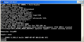
Open another Windows DOS prompt and telnet 127.0.0.1 1001.

We can see the whole installation process until it reboots when it's done.


After JunOS installation is complete we can login to Olive for the first time with root account and no password.


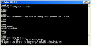
From BSD prompt, type 'cli' to go to JunOS prompt, then assign the IP address 10.1.1.2/8 to fxp0
root@%cli
root>edit
[edit]
root#
Create password for the root account, then set the IP address
[edit]
root#set system root-authentication plain-text-password
New password:
Retype new password:
[edit]
root#set interface fxp0 unit 0 family inet address 10.1.1.2/8
[edit]
root#commit
commit complete
If everything is set up properly, we should have connectivity from Olive from fxp0 interface to Windows Tap 1 interface.

Later we can install Kqemu to improve the performance:
- download kqemu from here, and extract it to a folder.
- Go to that folder, then the kqemu folder within it, and right click on kqemu.inf, and select install.
- from windows prompt type 'net start kqemu'
C:\>net start kqemu
The KQEMU virtualisation module for QEMU service was started successfully.
Now we can start Olive using Jqemu with additional kernel-kqemu option:
C:\qemu>jqemu.exe -L . -m 256 -hda Olive.img -serial telnet::1001,server -kernel-kqemu -localtime -net nic,vlan=1,macaddr=00:aa:00:00:01:01,model=i82559er -net tap,vlan=1,ifname=Tap1


